Sometimes, one expects or desires that the box vectors are aligned with Cartesian axes. As a simple example, if you start from a unit cell and duplicate it to form a supercell, then the crystal directions remain the same, but the box vectors change. Note that the Cartesian frame (X,Y,Z) is defined by convention and does not change.įinally, the vectors of the simulation box may also rotate, or be changed depending on one wants to achieve. (b) If the crystal is rotated by 45°, then it is the crystal axis that becomes aligned with the Cartesian X axis. fcc) is created with its crystal axis aligned with the Cartesian X direction, aligned with Y, and aligned with Z (the latter is not represented, it would point out of the figure). (a) By default, a unit cell of a perfect crystal (e.g. For the sake of brevity, the orientation of the crystal with respect to Cartesian directions is often noted with an equal sign, like X=, or Z=. Or, one may desire that the axis of the crystal lies along the Cartesian Z direction, and so on. For instance, one may rotate the crystal, so that the crystal axis becomes aligned with the Cartesian X direction. A crystal may have its axis aligned with the Cartesian X axis, but that does not have to always be the case.

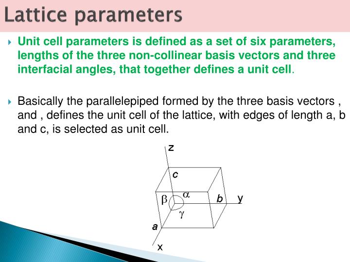
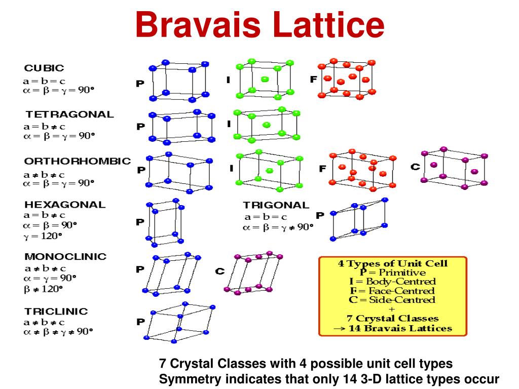
It is possible to rotate the crystal, which will cause the crystal axes to change with respect to the (fixed) Cartesian directions. Then, inside this Cartesian space, the crystal axes point in directions that are defined by crystallography. They represent the rigid and unmoveable metric of space, in the sense of Newton's absolute space: independent of time, and independent of what happens inside that space, whether or not you add atoms, rotate your crystal or whatever. they are chosen arbitrarily at the beginning of the problem, and never change afterwards. First, the Cartesian axes X, Y, Z are defined by convention, i.e. It is imperative to differentiate these vectors and directions. This is often the representation made by textbooks, and it can cause confusion in the minds of beginners -like, as I have read sometimes, writing that is the "X direction of the crystal", which can only lead to errors and misunderstandings. When constructing a unit cell of a cubic material, those three sets of vectors are basically identical: the crystal direction is aligned with the X axis, the direction with the Y axis, and with Z, and the box vectors are exactly equal to the lattice vectors. Finally, one can also define simulation box vectors, hereafter noted H 1, H 2, H 3.For cubic lattices, the vector noted, where h, k and l are integers, is the vector h a 1+ k a 2+ l a 3, where a 1, a 2 and a 3 are the base vectors of the lattice. When a crystal is considered, vectors along crystallographic directions can be given using Miller notation.The Cartesian directions X, Y, Z, associated with the unit vectors e x e y e z.In a simulation, three different sets of vectors can be distinguished, and must not be confused with one another: For that reason, let us define clearly some key concepts. ▶ For more information, refer to the corresponding documentation page.Ĭrystal orientation can be a tricky concept as it requires a good 3-D representation of a crystal, its directions and planes, which can be confusing at first for students and beginners.

It is recommended to be familiar with crystallography and Miller indexing to follow this tutorial.
MEASURE LATTICE PARAMETERS IN CRYSTALMAKER HOW TO
This tutorial explains how to use Atomsk to construct systems with any arbitrary crystallographic orientation, using the mode "-create", and/or the options "-rotate", "-orthogonal-cell", and "-reduce-cell".


 0 kommentar(er)
